This section presents the methodological framework employed by InferenceVision for transforming object detections obtained from raster imagery into precise geographic coordinates. The methodology integrates deep learning–based object detection with geospatial reference system handling and spatial transformations, enabling reliable conversion from image space to real-world geographic coordinates.
The overall workflow is designed to be modular, reproducible, and scalable, allowing it to operate on very high–resolution (VHR) satellite or aerial imagery. The pipeline consists of three primary stages: coordinate reference system normalization, normalized object center computation, and geographic coordinate derivation.
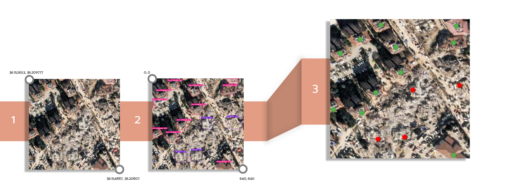
Coordinate Reference System Normalization (EPSG:4326)
InferenceVision requires all spatial data to be represented in a consistent geographic coordinate reference system. The target CRS is WGS 84 (EPSG:4326), which expresses locations using latitude and longitude and is widely adopted in geospatial analysis and web mapping applications.
Input raster datasets may originate from various projected or geographic coordinate systems. Spatial metadata and raster bounds are transformed into EPSG:4326, ensuring that all subsequent geographic coordinates are expressed in a consistent latitude–longitude reference system.
After reprojection, the geographic extent of the raster is extracted as a bounding polygon. The top-left (TL) and bottom-right (BR) corner coordinates of this polygon serve as spatial reference points for subsequent coordinate calculations.
Normalized Object Center Computation
Starting from InferenceVision v1.3, object centers are obtained directly from the detection model output. Modern YOLO architectures return bounding boxes in center format, eliminating the need for manual centroid calculation from corner coordinates.
Each detection is represented as:
Where:
- $x_c$: x-coordinate of the bounding box center
- $y_c$: y-coordinate of the bounding box center
- $w$: bounding box width
- $h$: bounding box height
The center coordinates are normalized relative to the image dimensions. This normalization enables a direct mapping between image space and geographic space regardless of image resolution.
Where:
- $N_x$: normalized horizontal coordinate
- $N_y$: normalized vertical coordinate
- $W$: image width (pixels)
- $H$: image height (pixels)
The normalized coordinates are interpreted as:
Geographic Coordinate Derivation
In the final stage, normalized object center coordinates are mapped to real-world geographic coordinates using the spatial extent of the raster. This mapping establishes a linear relationship between image coordinates and geographic coordinates within the transformed WGS 84 reference system.
Using the top-left and bottom-right corner coordinates of the raster’s geographic bounding polygon, longitude and latitude values for each detected object are computed through linear interpolation.
Where:
- $\text{lon}, \text{lat}$: Geographic coordinates of the detected object
- $N_x, N_y$: Normalized object center coordinates
- $lon_{TL}, lat_{TL}, lon_{BR}, lat_{BR}$: Geographic coordinates of the raster corner points
The interpolation assumes a linear relationship between image-space coordinates and geographic coordinates over the image extent. This approach enables detected objects to be accurately referenced within GIS systems, spatial databases, and interactive mapping platforms.
Implementation and Model Details
Object detection within InferenceVision is implemented using models provided by the Ultralytics framework, including YOLO-based architectures optimized for high-speed inference and high-resolution imagery. These models are well-suited for geospatial applications due to their balance between accuracy and computational efficiency.
Important: Input raster images must contain valid spatial reference metadata and an explicitly defined CRS to ensure correct geographic coordinate computation.
Apply the Methodology
Follow a practical, step-by-step example demonstrating the full InferenceVision pipeline from object detection to geographic coordinate extraction.
View Usage Guide